
Understanding Feeds, Speeds and Tooling A Beginner’s Guide
Clean, reliable CNC cutting depends on three things working together: how quickly the cutter moves, how fast it rotates and whether the tool suits the material. This guide explains the relationship without unnecessary complexity.
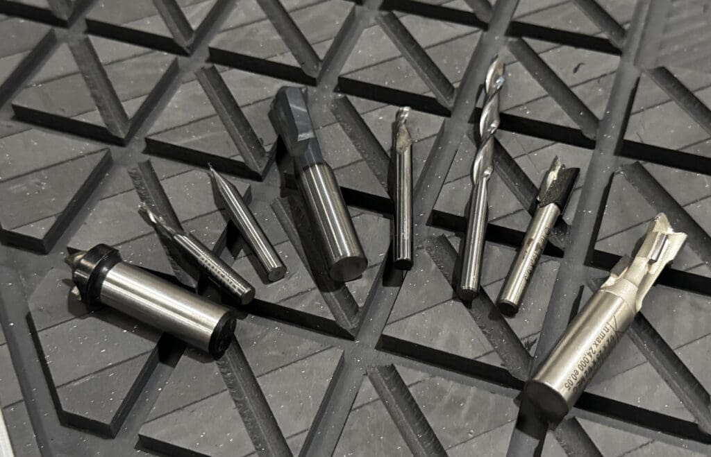
Feeds, speeds and tooling may sound technical, but they describe a simple balance: how quickly the tool moves through the material, how quickly it spins and how each cutting edge removes the resulting chip.
The three parts of every successful cut
The CNC router, material and cutter interact throughout the job. Changing one part of the process affects the others, which is why increasing speed or power without considering the complete setup can make the result worse.
A good starting point should come from the cutter manufacturer, machine supplier and previous proven jobs. The operator can then make controlled adjustments based on the sound, chips and finished edge.
The aim is not to find the fastest possible setting. It is to find a stable setting that cuts cleanly, clears chips and protects the tool.
Feed rate
How quickly the cutter travels through the material during machining.
Spindle speed
How quickly the tool rotates, normally stated in revolutions per minute.
Tooling
The cutter diameter, geometry, flute count and condition used for the job.
Chip load
The amount of material removed by each cutting edge on each revolution.
What is feed rate?
Feed rate is the speed at which the cutter moves through the material. It may be displayed in millimetres per second or metres per minute, depending on the controller and software.
If the feed is too slow for the selected spindle speed, the cutter may rub rather than remove a healthy chip. This creates heat, burning and premature wear.
What is spindle speed?
Spindle speed is how quickly the cutter rotates, measured in RPM. Higher RPM does not automatically produce a cleaner cut.
If rotation is too high compared with the feed rate, each cutting edge removes very little material and may generate more friction than useful cutting.
Feed rate and spindle speed must stay in balance
A slow feed combined with high RPM can create heat and scorched edges. An aggressive feed combined with insufficient spindle speed, excessive pass depth or unsuitable tooling can create chatter, poor finish and cutter failure. Adjustments should be small and recorded so the cause of each change remains clear.
Choosing the right cutter for the job
Tool selection affects chip removal, edge finish, cutting forces and tool life. The material, finished face, depth of cut and hold-down should all influence the decision.
Pull chips upwards efficiently but may create breakout on the upper face.
Push chips downwards and can produce a cleaner visible top edge.
Combine cutting directions to protect both faces of laminated boards.
Provide more space for chip clearance in materials such as plastics and aluminium.
Flute count affects chip clearance
Each flute is a cutting edge. Adding more flutes means more cutting edges pass through the material during every revolution, but there is less space between them for chips to escape.
Two-flute cutters are commonly used for wood-based materials, while a single-flute tool can support chip evacuation in plastics and non-ferrous materials.
Cutter condition matters as much as cutter type
A correct but blunt cutter can still produce burning, fuzzy edges, chatter and higher spindle load. Inspect cutting edges and replace worn tools before they damage an important sheet.
Keep collets clean and in good condition so the cutter is held securely and concentrically.
Understanding chip load
Chip load connects the feed rate, spindle speed and number of flutes. It describes how much material each cutting edge removes each time it passes through the cut.
When the chip load is too low, the tool can rub, generate heat and create very fine dust. When it is too high, the cutter may be overloaded and produce chatter, deflection or breakage.
You do not need to memorise every calculation, but you should understand that every cutting edge needs to remove a suitable chip.
Healthy chips
Defined chips generally indicate that the cutter is removing material effectively.
Very fine dust
Can indicate rubbing, a blunt cutter or insufficient feed for the selected RPM.
Heavy chatter
May indicate excessive tool load, weak hold-down or an unsuitable strategy.
Heat and melting
Suggests that chips are not being removed before they are recut or overheated.
Start with reliable recommendations
Use the cutter manufacturer’s feed, speed and pass-depth recommendations as a starting point. Confirm that the figures relate to the correct diameter, flute count, material and machine type.
Saved settings from a proven job are useful, but tool condition and different material batches may still require small changes.
Change one variable at a time
Altering feed rate, spindle speed and pass depth simultaneously makes it difficult to understand which change improved the cut.
Use a small test piece, make one controlled adjustment and record the result before continuing.
Signs that the setup may need attention
- Scorched edges or an unusual amount of heat.
- Fine dust instead of clearly formed chips.
- Chatter, rattling or a strained cutting sound.
- Fuzzy, chipped or melted finished edges.
- Tools wearing or breaking unusually quickly.
- Material movement or poor vacuum hold-down.
A sensible adjustment order
- Confirm the material and cutter specification.
- Check the cutter and collet condition.
- Verify hold-down, extraction and chip clearance.
- Review feed, RPM, pass depth and stepover.
- Run a small test and listen to the cut.
- Save the successful settings for future use.
Different materials need different approaches
There is no universal feed and speed setting. The correct approach depends on the cutter, material, thickness, machine and required finish.
MDF
Can machine efficiently but produces fine dust and requires effective extraction.
Plywood
Glue layers, veneers and voids can affect edge quality and cutter load.
Acrylic
Needs good chip clearance and heat control to prevent melting and rewelding.
Aluminium
Requires suitable tooling, controlled engagement and effective chip evacuation.
Common beginner mistakes
Most early problems come from treating feeds, speeds and tooling as separate settings rather than parts of the same cutting process.
Creates rubbing, heat, burnt edges and premature tool wear.
Can create chatter, deflection, inaccurate parts and cutter breakage.
Leads to poor chip clearance, tear-out, melting or an unsuitable edge finish.
Allows chips to be recut, generating heat and reducing surface quality.
Experience turns settings into understanding
Feeds and speeds are not simply numbers copied into the software. They describe how the cutter, material and machine interact.
Machines such as the Olympus ATC CNC router and Pegasus ATC CNC router provide the power and control needed for production work, but suitable tooling and informed settings determine how effectively that capability is used.
A good cut should look right, sound steady and remove material without unnecessary heat or strain.
Need help choosing the right CNC router?
Speak to the Opus CNC team about your materials, tooling requirements, production goals, machine specification, installation and operator training.